 English


Testing the Polarity of Current Transformers for Accurate Measurements and Diagnostics
Understanding Current Transformer Polarity Testing
Current transformers (CTs) are crucial components in electrical systems, primarily used for measurement and protection. They transform high primary current into a manageable secondary current, enabling safe monitoring of electricity usage and protection of equipment from overloads. One of the critical aspects of working with current transformers is ensuring correct polarity, which plays a vital role in the accurate operation of protective relays and metering devices. This article explores the importance of current transformer polarity testing and the methods used to perform this essential task.
Importance of Current Transformer Polarity
Polarity in current transformers refers to the phase relationship between the primary current (the current flowing in the high-voltage side) and the secondary current (the output of the transformer). Correct polarity ensures that the secondary output is in phase with the primary current. This phase relationship is especially important in applications such as differential protection schemes, where the current in two or more transformers needs to be compared. If the polarity is incorrect, it can lead to misoperation of protective relays, causing either nuisance tripping or failure to trip when an actual fault occurs.
In metering applications, incorrect polarity can result in erroneous readings, leading to billing inaccuracies. Therefore, polarities must be verified and tested before deploying current transformers in an electrical system.
Methods for Testing Current Transformer Polarity
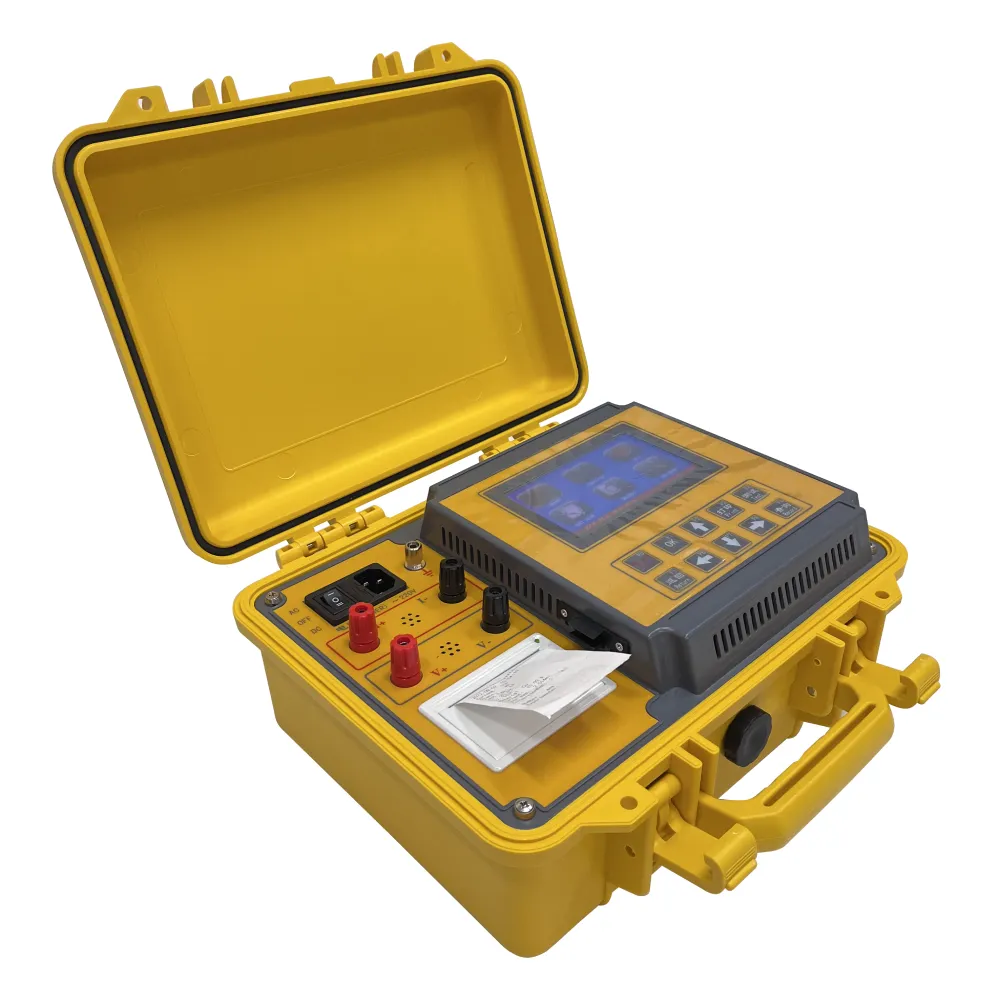
current transformer polarity test

There are several methods to test the polarity of current transformers. The most common and effective is the visual inspection of the polarity marks followed by a functional test.
1. Visual Inspection Before performing a functional test, a physical inspection of the current transformer for polarity markings is essential. Most CTs have clear markings or coloring, typically indicating the 'H1' (high voltage side) and 'H2' (low voltage side) terminals. The secondary terminals are often marked 'X1' and 'X2'. It is crucial to ensure that these markings are correctly aligned according to the wiring diagrams provided by the manufacturer.
2. Functional Testing This method involves connecting the secondary terminals of the CT to a test device. The primary circuit should carry an AC current, while the secondary terminals should be measured using an ammeter or a comparable measuring instrument. The polarity is deemed correct if the current flow from X1 matches the expected direction according to the primary current. Any reversal in the current direction at the secondary side indicates a polarity issue.
3. Use of Polarity Testers Specialized devices, known as polarity testers, can facilitate the polarity testing process. These testers are designed to apply a known current while measuring the resulting secondary current, providing a clear indication of any polarity discrepancies.
Conclusion
Polarity testing of current transformers is a fundamental procedure that ensures the reliable operation of electrical systems in which they are employed. By verifying the correct connection of CTs, engineers can prevent operational failures and enhance the safety and accuracy of electrical measurements. Implementing effective testing methods and adhering to proper installation practices will help maintain the integrity of electrical installations, ultimately leading to successful performance and longevity of protective devices. In the ever-evolving field of electrical engineering, understanding and testing CT polarity remains an indispensable skill for professionals working in power systems.
-
Differences between open cup flash point tester and closed cup flash point testerNewsOct.31,2024
-
The Reliable Load Tap ChangerNewsOct.23,2024
-
The Essential Guide to Hipot TestersNewsOct.23,2024
-
The Digital Insulation TesterNewsOct.23,2024
-
The Best Earth Loop Impedance Tester for SaleNewsOct.23,2024
-
Tan Delta Tester--The Essential Tool for Electrical Insulation TestingNewsOct.23,2024


