 English


Designing a Simple Inductor Testing Circuit for Accurate Component Measurements and Evaluations
Understanding Inductor Tester Circuits
Inductors, though simple components, play a crucial role in various electronic circuits, particularly in power supplies, filters, and oscillators. As devices that store energy in a magnetic field when electrical current passes through them, inductors can exhibit varying characteristics depending on their design and materials. To ensure that inductors are functioning correctly, an inductor tester circuit can be employed, allowing engineers and hobbyists to measure parameters such as inductance, quality factor (Q), and series resistance.
The Importance of Inductor Testing
Inductors can degrade over time or be misused, leading to performance issues in electronic circuits. Testing inductors ensures that they meet their specifications and remain reliable in applications. An inductor tester circuit can provide critical information about an inductor’s inductance value, which is typically measured in henries (H), as well as its efficiency and operational quality through the Q factor. A higher Q factor indicates lower energy losses, making the inductor more efficient for use in various applications.
Basic Components of an Inductor Tester Circuit
An inductor tester circuit generally consists of several key components
1. Oscillator The heart of the tester is an oscillator that generates an alternating current (AC) signal at a known frequency. This frequency is crucial in determining the inductance as it affects the reactance of the inductor.
2. Measurement Circuit The AC signal generated by the oscillator is applied to the inductor under test. The circuit includes a method to measure the resulting voltage and current through the inductor. This can be done using operational amplifiers or microcontroller analog-to-digital converters (ADCs).
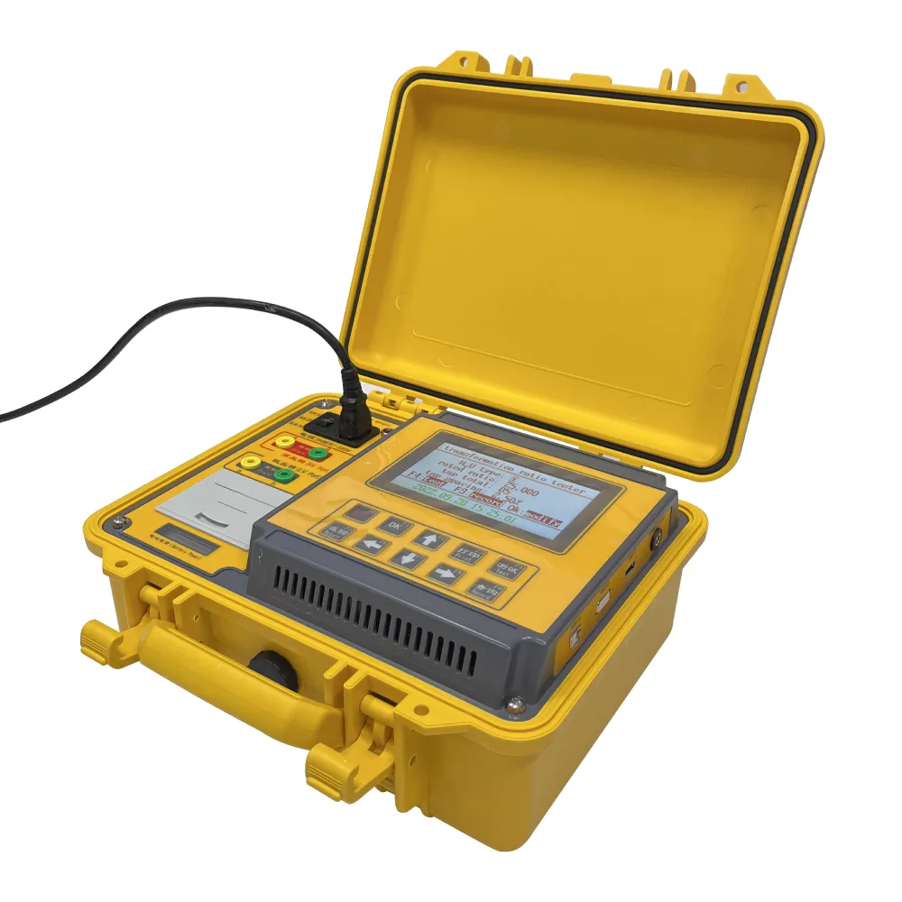
inductor tester circuit

3. Microcontroller or Display For modern circuits, a microcontroller can be employed to process the measurements. It calculates the inductance using the formula \( L = V/I \) (reactance = voltage/current) and displays the results on an LCD or LED screen.
4. Coarse and Fine Adjustments Many inductor testers are equipped with controls to allow users to fine-tune the frequency of the oscillator or adjust for specific ranges of measurement, enhancing the accuracy of the results.
Working Principle
The working principle behind an inductor tester circuit is based on the relationship between voltage, current, and inductance. When an AC voltage is applied to an inductor, it reacts to this voltage by creating a magnetic field. The inductor's inductive reactance depends on both the frequency of the applied voltage and the inductance value. The tester calculates the inductance by measuring the voltage across the inductor and the current flowing through it, applying Ohm's law and the formula for inductive reactance.
Practical Applications
Inductor tester circuits can be found in various environments, from laboratories to production lines. In designing circuits, engineers frequently use these testers to evaluate inductors, ensuring that they meet operational standards and are suitable for their intended applications. Additionally, hobbyists and electronics enthusiasts can utilize simple inductor testers for personal projects, allowing them to assess components salvaged from older devices or as part of DIY electronics projects.
Conclusion
Inductor tester circuits are invaluable tools for accurate measurement and evaluation of inductors. With the right components and principles in place, these circuits can provide detailed information about an inductor’s performance, helping in the design and maintenance of electronic systems. Understanding how to build and operate an inductor tester enhances an engineer’s ability to ensure the reliability and efficiency of their designs, paving the way for innovation in electronics.
-
Differences between open cup flash point tester and closed cup flash point testerNewsOct.31,2024
-
The Reliable Load Tap ChangerNewsOct.23,2024
-
The Essential Guide to Hipot TestersNewsOct.23,2024
-
The Digital Insulation TesterNewsOct.23,2024
-
The Best Earth Loop Impedance Tester for SaleNewsOct.23,2024
-
Tan Delta Tester--The Essential Tool for Electrical Insulation TestingNewsOct.23,2024


