 English


Earth Ground Resistance Tester
Understanding Earth Ground Resistance Testers
In the realm of electrical engineering and safety, maintaining a proper grounding system is fundamental. A critical tool in this process is the earth ground resistance tester. This device is utilized to measure the resistance of the ground connection of various electrical systems, ensuring that they perform efficiently and safely.
What is Ground Resistance?
Ground resistance refers to the impedance that an electrical current encounters when traveling through the ground. A low ground resistance means that the grounding system can dissipate electrical currents effectively, preventing electrical shocks, equipment damage, and potential fire hazards. Grounding systems are essential for protecting both individuals and devices, particularly in installations with high voltages or sensitive electronics.
The Importance of Ground Resistance Testing
Regular testing of a grounding system is not just a recommendation; in many industries, it is a legal requirement to ensure safety. The performance of equipment can degrade over time due to environmental factors, corrosion, or physical damage. By measuring ground resistance, technicians can identify potential issues before they escalate into dangerous situations.
The National Electrical Code (NEC) and other regulatory bodies stipulate acceptable ground resistance levels. Typically, a resistance reading of 5 ohms or less is considered ideal for efficient grounding systems. However, in critical applications, such as hospitals or data centers, even stricter limits may apply.
How Does an Earth Ground Resistance Tester Work?
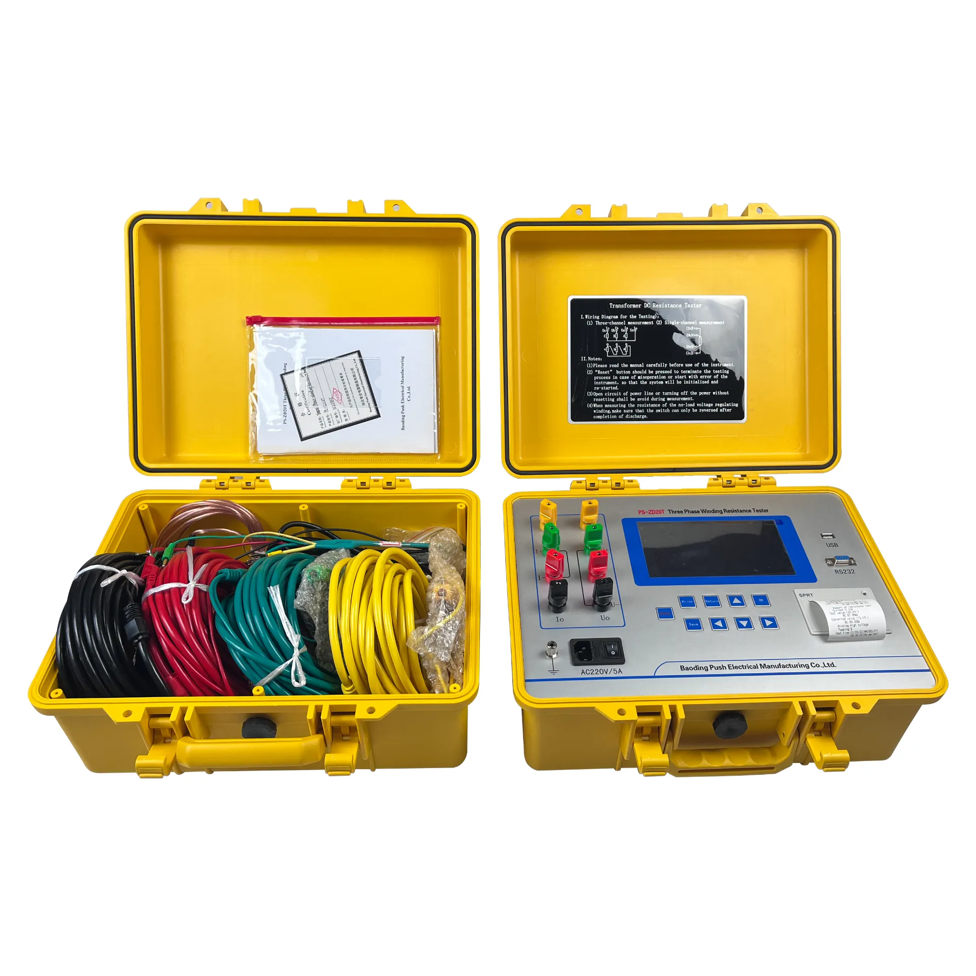
earth ground resistance tester

An earth ground resistance tester works on various principles. The most common method involves the use of the three-pole fall of potential method or the two-pole method. In these methods, the tester introduces a known small current into the ground through a pair of electrodes. It then measures the voltage drop that occurs across an additional electrode, allowing it to calculate the resistance based on Ohm's law (Resistance = Voltage / Current).
1. Three-Pole Method This method involves using three stakes one for current injection, one for potential measurement, and one to measure reference potential. It provides accurate and reliable readings of ground resistance.
2. Two-Pole Method While simpler, this method can be less accurate due to potential errors caused by stray currents. It is better suited for quick checks rather than precise readings.
Features of Earth Ground Resistance Testers
Modern earth ground resistance testers come equipped with a variety of features that enhance their usability and accuracy
- Digital Readouts Offering clear and precise readings of resistance values. - Data Logging Many models can store data for later analysis, making it easier to track changes over time. - Built-in Printing Some testers can print reports on-site, which is beneficial for record-keeping and compliance purposes. - Multiple Measurement Modes Advanced testers provide different modes tailored for various testing scenarios, including noise immunity for more reliable readings.
Conclusion
Earth ground resistance testers are indispensable tools in ensuring electrical safety and compliance. Regular testing of grounding systems can significantly reduce the risks associated with electrical faults, safeguarding both lives and equipment. By understanding the importance of these devices and utilizing them effectively, electrical professionals can contribute to safer and more reliable electrical systems. Whether in commercial, industrial, or residential settings, prioritizing ground resistance testing is vital for any responsible electrical maintenance protocol.
-
Differences between open cup flash point tester and closed cup flash point testerNewsOct.31,2024
-
The Reliable Load Tap ChangerNewsOct.23,2024
-
The Essential Guide to Hipot TestersNewsOct.23,2024
-
The Digital Insulation TesterNewsOct.23,2024
-
The Best Earth Loop Impedance Tester for SaleNewsOct.23,2024
-
Tan Delta Tester--The Essential Tool for Electrical Insulation TestingNewsOct.23,2024


