 English


Testing Transformers with a Multimeter for Effective Voltage and Current Analysis Techniques
Testing Transformers Using a Multimeter A Comprehensive Guide
Transformers play a crucial role in electrical power distribution and various electrical applications by stepping up or stepping down voltage levels. Ensuring their operational integrity is paramount, and one of the most efficient tools for testing transformers is the multimeter. This article delves into how to effectively test transformers using a multimeter, providing insights into safety protocols, testing procedures, and interpretative methods.
Understanding the Transformer
Before diving into the testing process, it’s essential to have a clear understanding of what a transformer is and its functionality. A transformer consists of primary and secondary windings wrapped around a ferromagnetic core. When alternating current (AC) flows through the primary winding, it creates a magnetic field that induces voltage in the secondary winding. Hence, if there are issues in either winding or the core, it can lead to failure in performance.
Safety Protocols
Safety should always be the number one priority when performing electrical tests. Here are a few essential safety measures
1. Disconnect Power Always ensure the transformer is disconnected from any power source before testing to avoid electric shocks. 2. Use Personal Protective Equipment (PPE) Wear insulated gloves, safety goggles, and appropriate clothing to protect against accidental contact or faults. 3. Check Multimeter Settings Configure your multimeter correctly (AC or DC, resistance, etc.) based on the specific test you are performing.
Testing Procedure
Testing a transformer with a multimeter can involve a few different procedures, including measuring resistance, checking for shorts, and evaluating voltage. Here are key steps involved
To test the winding condition of the transformer, resistance measurements are taken
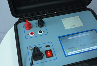
transformer testing using multimeter

- Disconnect the Transformer Ensure that it is completely powered off. - Set the Multimeter to Resistance (Ω) Mode Connect the multimeter leads to the primary winding terminals. - Record the Reading A healthy winding usually shows a low resistance value, indicating good connectivity. Compare it with the manufacturer’s specifications. - Repeat for the Secondary Winding Follow the same process for the secondary winding.
2. Checking for Short Circuits
This step helps determine if there are any shorts within the windings.
- Set the Multimeter to Continuity (Buzzer Mode) Connect the leads to the winding terminals. - Listen for the Buzzer A continuous beep indicates a short circuit, while silence suggests good integrity.
3. Voltage Testing
Once the winding resistance and integrity are confirmed, voltage testing is vital to ensure functionality.
- Reconnect the Transformer to Power With power restored, ensure all safety precautions are still in place. - Set the Multimeter to Voltage (AC) Mode Measure voltage across the primary terminals and the secondary terminals. - Compare with Specifications Check if the readings correspond to the expected input and output voltages as per the transformer's ratings.
Interpreting Results
After completing the tests, analyzing the data collected is crucial. Any resistance that appears too high may indicate poor electrical connections or damage, while any continuity found in unexpected areas suggests severe internal faults. Voltage discrepancies may point toward malfunctioning windings or improper transformer design.
Conclusion
Testing transformers using a multimeter is a vital practice for maintaining electrical systems’ integrity and safety. By following systematic procedures and adhering to safety protocols, technicians can effectively diagnose and rectify issues with transformers, ensuring they operate efficiently and reliably. Regular testing not only prolongs the lifespan of transformers but also protects the broader electrical system from potential failures, safeguarding both equipment and personnel.
-
Differences between open cup flash point tester and closed cup flash point testerNewsOct.31,2024
-
The Reliable Load Tap ChangerNewsOct.23,2024
-
The Essential Guide to Hipot TestersNewsOct.23,2024
-
The Digital Insulation TesterNewsOct.23,2024
-
The Best Earth Loop Impedance Tester for SaleNewsOct.23,2024
-
Tan Delta Tester--The Essential Tool for Electrical Insulation TestingNewsOct.23,2024


