TEL:
+86-0312-3189593
 English

Telephone:0312-3189593

Email:sales@oil-tester.com
2 月 . 04, 2025 05:57
Back to list
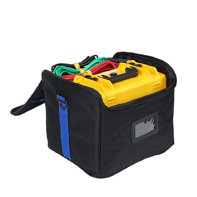
PS-SC03 Three Phase Secondary Current Injection Kit
Conducting a three-phase transformer continuity test is a crucial step in ensuring the reliable operation and longevity of electrical distribution systems. With years of hands-on experience in the electrical engineering field, I've witnessed the importance of precise testing methods in preventing costly downtimes and equipment failures. Here’s an authoritative guide to performing a continuity test on a three-phase transformer, packed with professional insight for those in the industry.
4. Document the Results It’s good practice to record each reading meticulously. This documentation can support trend analysis and predictive maintenance decisions. 5. Analysis and Action If discrepancies are noted, further investigation may be required using advanced diagnostic tools such as insulation resistance testers or thermal imaging cameras to localize defects. Expert proficiency and astuteness in identifying anomalies can make a significant impact on the maintenance and management of electrical systems. Often, those tiny variances in readings signal potential issues that, left unchecked, might escalate. This continuity test, while fundamental, demands a blend of technical expertise, acute observational skills, and a conscientious approach to safety protocols. Understanding the pivotal role of routine testing and documentation fosters trust within your team and with stakeholders, ensuring systems operate at peak performance without unexpected disruptions. Trustworthiness stems from not only performing these tests but thoroughly understanding their implications for the system's health. As we advance in electrical engineering, refining our testing techniques and staying abreast of technological advancements will further cement our standing as authoritative figures in transformer maintenance and care. This guide provides an experienced perspective, underscoring authoritative insights essential to mastering three-phase transformer continuity tests—your foundation for reliability in electrical distribution systems.


4. Document the Results It’s good practice to record each reading meticulously. This documentation can support trend analysis and predictive maintenance decisions. 5. Analysis and Action If discrepancies are noted, further investigation may be required using advanced diagnostic tools such as insulation resistance testers or thermal imaging cameras to localize defects. Expert proficiency and astuteness in identifying anomalies can make a significant impact on the maintenance and management of electrical systems. Often, those tiny variances in readings signal potential issues that, left unchecked, might escalate. This continuity test, while fundamental, demands a blend of technical expertise, acute observational skills, and a conscientious approach to safety protocols. Understanding the pivotal role of routine testing and documentation fosters trust within your team and with stakeholders, ensuring systems operate at peak performance without unexpected disruptions. Trustworthiness stems from not only performing these tests but thoroughly understanding their implications for the system's health. As we advance in electrical engineering, refining our testing techniques and staying abreast of technological advancements will further cement our standing as authoritative figures in transformer maintenance and care. This guide provides an experienced perspective, underscoring authoritative insights essential to mastering three-phase transformer continuity tests—your foundation for reliability in electrical distribution systems.
Previous:
Latest news
-
Differences between open cup flash point tester and closed cup flash point testerNewsOct.31,2024
-
The Reliable Load Tap ChangerNewsOct.23,2024
-
The Essential Guide to Hipot TestersNewsOct.23,2024
-
The Digital Insulation TesterNewsOct.23,2024
-
The Best Earth Loop Impedance Tester for SaleNewsOct.23,2024
-
Tan Delta Tester--The Essential Tool for Electrical Insulation TestingNewsOct.23,2024


