TEL:
+86-0312-3189593
 English


Telephone:0312-3189593

Email:sales@oil-tester.com

3 月 . 06, 2025 11:37
Back to list
inductor tester circuit
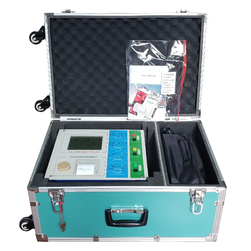
Navigating the realm of electrical components often brings engineers and hobbyists alike to the topic of testing inductors. In this specialized field, having a reliable inductor tester circuit is indispensable. Understanding its intricacies not only requires technical know-how but also emphasizes the importance of precise measurement and evaluation for improved circuit functionality.
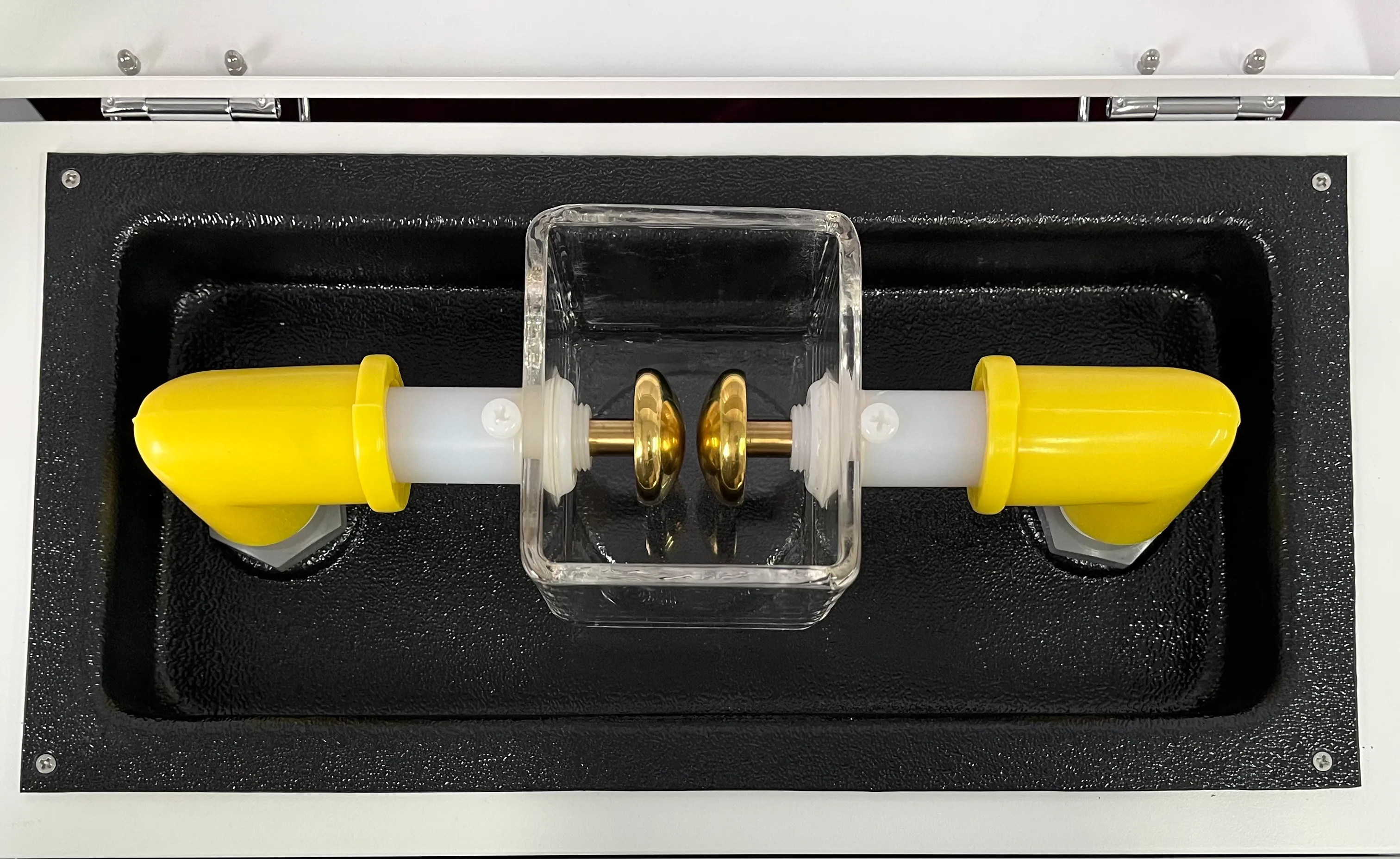
Expertise in electronics reveals further intricacies that elevate a tester’s performance. The incorporation of precision components such as operational amplifiers (Op-Amps), capable of offering zero-drift and low noise, significantly sharpens measurement reliability. Similarly, sourcing high-quality connectors and PCBs ensures stable connections and mitigates signal degradation. Real-world experience underscores the transformative potential of a well-designed inductor tester circuit. Engineers equipped with these testers can diagnose and resolve issues such as coil mismatches in transformers or chokes, leading to improved energy efficiency and reduced interference in electronic devices. Such proficiency is pivotal in industries ranging from telecommunications to automotive electronics, where precision and reliability are non-negotiable. Moreover, experts seeking to harness the full potential of inductor testing should focus on calibration. Conducting regular calibrations against known standards ensures the tester maintains precision over time, thus augmenting its trustworthiness. Ultimately, the authoritative stance gained from mastering inductor tester circuits translates into innovation and efficiency. Advanced testers, incorporating both hardware capabilities and sophisticated software algorithms, empower users to explore inductance with unprecedented depth. This allows not only for routine verification of performance but also for the discovery of new applications across various domains of electrical engineering. In conclusion, the journey through understanding and utilizing an inductor tester circuit can embody the principles of Experience, Expertise, Authoritativeness, and Trustworthiness. This journey offers enriching insights into the pivotal role inductance plays in modern electronics and provides the practical instruments needed to push the boundaries of technology further.
Expertise in electronics reveals further intricacies that elevate a tester’s performance. The incorporation of precision components such as operational amplifiers (Op-Amps), capable of offering zero-drift and low noise, significantly sharpens measurement reliability. Similarly, sourcing high-quality connectors and PCBs ensures stable connections and mitigates signal degradation. Real-world experience underscores the transformative potential of a well-designed inductor tester circuit. Engineers equipped with these testers can diagnose and resolve issues such as coil mismatches in transformers or chokes, leading to improved energy efficiency and reduced interference in electronic devices. Such proficiency is pivotal in industries ranging from telecommunications to automotive electronics, where precision and reliability are non-negotiable. Moreover, experts seeking to harness the full potential of inductor testing should focus on calibration. Conducting regular calibrations against known standards ensures the tester maintains precision over time, thus augmenting its trustworthiness. Ultimately, the authoritative stance gained from mastering inductor tester circuits translates into innovation and efficiency. Advanced testers, incorporating both hardware capabilities and sophisticated software algorithms, empower users to explore inductance with unprecedented depth. This allows not only for routine verification of performance but also for the discovery of new applications across various domains of electrical engineering. In conclusion, the journey through understanding and utilizing an inductor tester circuit can embody the principles of Experience, Expertise, Authoritativeness, and Trustworthiness. This journey offers enriching insights into the pivotal role inductance plays in modern electronics and provides the practical instruments needed to push the boundaries of technology further.
Previous:
Latest news
-
Differences between open cup flash point tester and closed cup flash point testerNewsOct.31,2024
-
The Reliable Load Tap ChangerNewsOct.23,2024
-
The Essential Guide to Hipot TestersNewsOct.23,2024
-
The Digital Insulation TesterNewsOct.23,2024
-
The Best Earth Loop Impedance Tester for SaleNewsOct.23,2024
-
Tan Delta Tester--The Essential Tool for Electrical Insulation TestingNewsOct.23,2024


